
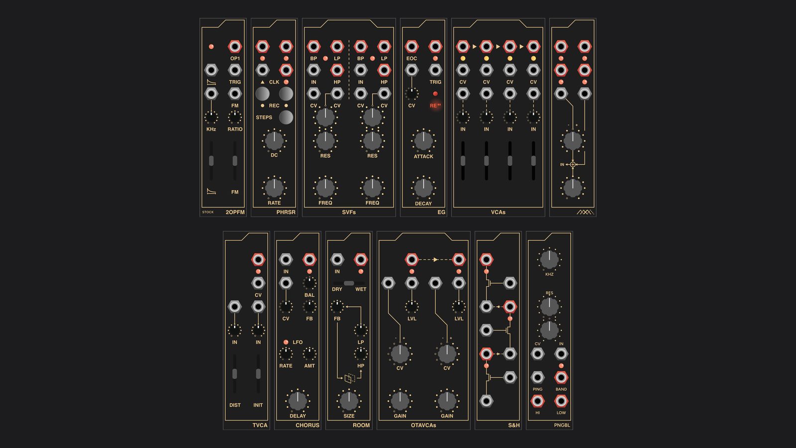
SFS Super is a VCV Rack port of the Eurorack library made by the designer Chris McDowell under the name Super Synthesis. Super Synthesis closed at the end of 2024, and Chris published the schematics, firmware and panel art for its modules, along with several designs that never went into production, as public domain under CC0. I ported them with his permission. It is a separate plugin from Signal Function Set, and it is not a Super Synthesis product.
The aim was to make each module behave the way the circuit or the firmware does, rather than to make a module that sounds roughly like it. The digital modules (2OPFM, PHRSR, CHORUS and ROOM) run their firmware at the chip’s own interrupt rates, with the original lookup tables and integer maths, so their quirks come along with them. The analog modules are modelled stage by stage from the schematics with the real component values, so ranges, curves and the odd behaviour at the ends of a knob’s travel come from the circuit. Each one is checked against its firmware or schematic by a test harness in the repository. Where I had to guess, because a schematic was missing or a value could not be read from it, I say so below.
The panels are the original Super Synthesis panel art. The knobs, jacks, sliders and buttons you click on are cut out of that art, so each module looks like the hardware it came from.
There are twelve modules. Nine of them were Super Synthesis products, and their Library pages link to the hardware on ModularGrid. The last three are unreleased designs from the archive.
2OPFM
A two-operator FM voice in 6 HP, and the module that started this port. The context menu picks the firmware. Stock is the firmware the module shipped with, emulated at its own 39.975 kHz interrupt with its envelope tick, its tables and its sample-and-hold DAC, so it has the grainy top end of the hardware. 2OPFM+ is the same instrument with calibrated V/OCT, a RATIO control that sticks on the integer ratios, and modulator feedback in the top quarter of the FM control.
The other four firmwares turn the module into something else. Modal drum is a struck membrane modelled mode by mode, morphing into a bar. CZ is Casio-style phase distortion, with FM working as the DCW. Formant is a FOF formant voice where RATIO chooses the vowel, and Bell is a 17-partial bell that also morphs into a bar. The tooltips rename the controls to suit whichever firmware is loaded.
The same five firmwares are written for the hardware too, and the code is in 2opfm-alt on GitHub. In theory you can flash them onto a real REV5 2OPFM with an ST-Link on the module’s programming header, either with STM32CubeProgrammer, the included OpenOCD script, or a page that flashes from Chrome over WebUSB. The all-in-one image holds all six firmwares, including the stock one, and you choose between them with the module’s own controls at power-up. I have not run any of it on a module yet. The DSP matches the VCV module sample for sample, but the firmware itself is untested on hardware, so try it on a module you are prepared to reflash. The Super Synthesis factory firmware is in the same repository and puts a module back exactly as it shipped.
PHRSR
PHRSR records two 16-step phrases live from one knob and plays them back on a clock. On the hardware you hold REC and turn the DC knob to record a phrase. A mouse cannot hold one control while it turns another, so in VCV the REC buttons latch on and light up until you press them again. The firmware’s timer interrupt is transcribed with its original integer types and runs at the chip’s 1422 Hz, which keeps the hardware’s habits: the knob smoothing stops a little short when rising, and an external clock edge that lands during a high internal clock steps twice. Sequences are saved with the patch.
SVFs
Two state-variable filters built on the 2164 VCA chip, each with low-pass, band-pass and high-pass outputs. FREQ tracks exactly 1V/oct and sweeps nearly twenty octaves, topping out at 24.1 kHz. Turn RES up and the filter self-oscillates, held to about 11 V peak to peak by a pair of zener diodes. At the very top of RES the resonance pot’s wiper grounds the clipping stage and the power rails limit the oscillation instead, and the model does the same. Self-oscillation starts from a small noise floor, the way the hardware starts from its own noise.
EG
A fast analog attack/decay envelope on an LM13700. A trigger starts the attack, which turns into the decay when the envelope crosses about 6 V. The red RE button switches between one-shot and re-trigger and lights the panel’s translucent RE window, and EOC sends a pulse as the envelope falls back to zero. The ATTACK control carries an offset in the circuit as drawn, which skews its range slow: under a millisecond at the fast end, about three and a half seconds in the middle, and minutes at the top. DECAY runs from a few milliseconds to about two minutes. The one value the schematic cannot give is the converter’s reference current, which depends on how well two transistors match, so I assumed they match.
VCAs
Four linear VCAs on the 2164, each with an attenuverter on its input and a slider plus CV for its gain. Unity gain is the ceiling. An output with nothing patched into it sums into the next channel, so the four chain into a mixer from left to right, and the last output carries everything that was left unpatched.
SCANNER
SCANNER is the control half of a four-way crossfader. One scan voltage, from the knob and two CV inputs, moves across four overlapping triangular windows about 7 V high, and each output rises and falls as the scan passes through its window. Patch the outputs into the four channels of VCAs and the scan voltage fades between four signals. The schematic does not say which jack is which output, so I numbered them in reading order.
TVCA
A two-input VCA on an LM13700 with tanh saturation. The two inputs pass through level trimmers and are summed, DIST sets how hard the OTA is driven, and INIT sets the gain, with CV adding to it. Even with DIST all the way down, a 5 V signal is compressed by about 2 dB, as it is on the hardware.
CHORUS
A modulated delay line that runs from chorus to a 300 ms echo, with inverted feedback. It is ported from the firmware at its own 49.95 kHz, including a lookup table that the firmware declares a few entries longer than it fills in, so RATE and AMT read zero at the very top of their travel. BAL is an analog crossfade between dry and wet, and the CV input moves the delay time through an attenuverter. The firmware hard-clips the delay line inside the feedback loop, which crackles with a hot signal and high feedback, so a soft clip is on by default and the context menu brings back the original clamp. There was no panel art and no schematic for CHORUS. I rebuilt the panel from the PCB’s gerber files and assumed a standard Eurorack effect’s input and output levels.
ROOM
An allpass reverb from its firmware: four input allpasses and three in the loop, all sharing one 15,000-sample buffer, with high-pass and low-pass filters in the loop and inverted feedback. ROOM uses the same short lookup table as CHORUS, so LP at the very top of its travel closes the loop’s filter and silences the wet signal. I kept that, and the context menu has an option to complete the table. The top of FB is the firmware’s own as well: the 16-bit rounding turns to grit from about 0.9, 0.98 nearly holds a sound forever, and at the very top the loop gain passes one and the reverb runs away to full scale.
OTAVCAs
The first of the unreleased designs. Two VCAs on LM13700s, each with a level control on its input and an attenuverted CV. The audio reaches the OTA through a divider that lets it saturate readily, so the module is as much a distortion as a VCA. Output 1, unpatched, sums into output 2.
S&H
Three JFET sample-and-holds, drawn on the panel as a chain running upwards, so the first channel is the bottom one. Each input is normalled from the output of the channel below. Each trigger input is normalled from the channel below’s trigger, inverted, so a single trigger samples the first channel on its rising edge, the second on its falling edge, and the third about half a millisecond after that. Feed it one signal and one gate and it steps a value up the chain.
PNGBL
A pingable filter: the state-variable loop from SVFs built on LM13700 integrators instead of the 2164, with a PING input that turns a rising edge into a short kick into the filter and sets it ringing. The design never had a panel, so the one in the plugin is provisional, built from the same frame as EG with its lettering drawn in, and the control positions come from the board’s pick-and-place file.
Installing
SFS Super is in the VCV Rack Library as its own plugin. Builds for every platform are also attached to each release on GitHub, where the source lives. The port’s code is GPL-3.0-or-later. The original designs, firmware and panel art are Super Synthesis’s, and are public domain.